EE2024 Assignment 2 Report (Excerpt)
Note
This is an excerpt of the project report containing only the portions which I wrote and which describe my contributions to the project.
1 Introduction
CUTE (Care Unit for The Elderly) is a system for monitoring the elderly to ensure their safety and security. Our system is a prototype of CUTE, built using Embedded Artist’s LPC1769 LPCXpresso board (EA-XPR-003) and LPCXpresso Base Board (EA-XPR-021). The base board comes with a host of sensors and actuators which are used to accomplish the system’s requirements.
2 Objectives
Our objectives are:
- Reliability -- being a system which continuously monitors an elderly person, CUTE must not break down even when powered on for an extremely long period of time.
- Responsiveness -- Having a system which responds quickly to user input would give the impression to end users that the system is of high quality.
Furthermore, the system needs to respond quickly to fire or movement in darkness as it could mean a difference between life or death for the elderly person being monitored.
3 System design and processes
3.1 Subsystems overview
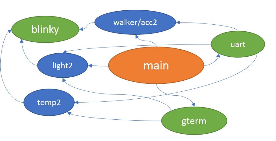
Our system consists of various subsystems which work together to accomplish its objectives. The significant subsystems are:
main-- Controls the main execution of our system. Transfers control of the processor to the various subsystems as required.hexsec-- Keeps track of the modulo-16 counter that increments every second. Notifies subsystems to run their periodic tasks. (gtermupdate when the counter is 5, 10 or 15, uart update when the counter is 15, update led 7 segment display with the counter value every 1s)
walker-- Detects movement based on accelerometer readings and notifiesblinky.acc2-- Oversees the accelerometer on the baseboard. Provides accelerometer sensor readings with minimal latency while minimizing I2C communication with the accelerometer.
temp2-- Oversees the temperature sensor on the baseboard. Provides continuous monitoring of temperature. Detects a fire based on readings from the temperature sensor and notifiesblinky.light2-- Oversees the light sensor on the baseboard. Retrieves the light sensor reading as needed for the OLED display. Responds to light sensor interrupts to detect low light conditions and notifiesblinky.gterm-- Controls the OLED display on the baseboard. Updates the display with information fromacc2,temp2,light2when prompted to byhexsec.blinky-- Controls the red, blue RGB LEDs on the baseboard. Blinks the red/blue LEDs with a 333ms interval if a fire/movement in darkness occurs.uart-- Handles communication over UART. Sends a status update with the values fromacc2,temp2,light2when prompted to byhexsec.
4 Implementation details
4.2 systick -- Millisecond counter
The systick subsystem provides a millisecond counter which increments every millisecond, implemented using the Cortex-M3’s systick timer.
Since the counter is stored in a 32-bit unsigned integer,
it will overflow every 4294967 seconds (49 days).
As CUTE will likely be powered on for more than 49 days,
our code must consider this overflow, especially when using the number of ticks to determine milliseconds elapsed.
We implemented a helper function systick_diff() to do this properly.
4.3 main -- Main loop
Only one slave can be communicated to at one time for I2C/SPI. If we preempt any I2C/SPI communication with another I2C/SPI communication, we may end up corrupting the transfer. As such, to ensure that only one I2C/SPI transfer occurs at any one time they are run on the main loop.
The main loop is divided into tasks, where each task has a flag. If the flag is set, then the task is run. Only one task can run at any time, and so ensuring that the worst-case execution time (WCET) of each task is as low as possible is extremely important in ensuring the system remains responsive.
| Task | Priority | Period | WCET (ms) |
|---|---|---|---|
| Communication with light sensor | 1 | On interrupt | 0 |
| Communication with accelerometer | 2 | ≈ 8ms | 1 |
| Communication with 7 segment display | 3 | 1s | 0 |
| Update OLED with accelerometer readings | 9 | 5-6s | 7 |
| Update OLED with light reading | 10 | 5-6s | 3 |
| Update OLED with temperature reading | 10 | 5-6s | 3 |
| UART communication | 12 | 16s | 3 |
| Save settings to EEPROM | 14 | On external input | 16 |
As shown in the table above, the worst WCET is only 16ms. This, coupled with the use of interrupts in our system for extremely critical tasks (e.g. fire, low light detection) means our system is extremely responsive.
4.4 Interrupt Priorities
| Name | Preempt Priority | Subpriority |
|---|---|---|
| Systick | 0 | 0 |
| EINT3 (GPIO) | 1 | 0 |
| EINT0 (sw3) | 1 | 1 |
| TIM0 (blinky) | 1 | 2 |
| TIM1 (hexsec) | 1 | 3 |
Our millisecond tick count, handled by the Systick interrupt, needs to be accurate as the accuracy of other subsystems (e.g. our temperature measurement subsystem) depends on it. As such, we have given it the highest preempt priority of 0.
The EINT3, EINT0, TIM0 and TIM1 interrupt handlers are quite short, and are likely not worth the overhead of preemption, and thus they are given the same preempt priority of 1. Out of these 4 interrupts, we have given EINT3 the highest subpriority since it must handle events which occur extremely frequently (e.g. the rising/falling edges of the temperature sensor). The next highest subpriority is given to EINT0, which handles switch 3, for responsiveness to user events. TIM0 is given the next highest subpriority, since it occurs every 333ms, while TIM1 is given the lowest subpriority since it only occurs every 1s.
Overall, we need 2 subpriority bits and at least 1 preempt priority bit, so we have chosen priority group 4 which gives us 3 preempt priority bits and 2 subpriority bits.
temp2 -- Fire detection subsystem
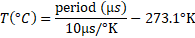
The MAX6576ZUT temperature sensor used on the baseboard converts the ambient temperature into a 50% duty cycle square wave with a period proportional to absolute temperature. Its time select pins (TS1, TS0) controls how much the period scales with temperature. For this project, we chose TS1=GND, TS0=GND, which gives us a scalar multiplier of 10µs/°K. This relatively low multiplier was chosen to ensure that the responsiveness of the subsystem does not degrade under higher temperatures.
We can calculate the temperature with:
However, the accuracy of the MAX6576 is susceptible to noise.
Furthermore, our most precise timer (systick) only counts in milliseconds.
To minimize the effects of this noise, as well as to bring our measurements into the millisecond range,
we use the average period of 170 cycles (NUM_HALF_PERIODS = 340) to calculate the temperature.
Every time a new temperature value is calculated, we check to see if it is higher than the fire temperature threshold (TEMP_HIGH_WARNING).
If it is, then we notify the blinky subsystem of the fire (blinky_enableFire()).
temp2 is implemented with interrupts to maintain the overall responsiveness of the system. See Section 6.1 (Provided temperature sensor code negatively impacted overall system responsiveness for more details).
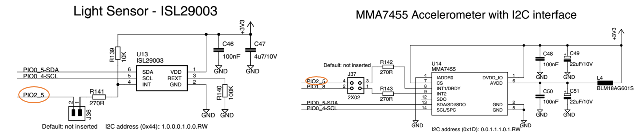
4.6 light2 -- Low light level detection subsystem
The light sensor (ISL29003) contains two photodiodes. Diode 1 is sensitive to both visible and infrared light, while Diode 2 is mostly sensitive to infrared light. The ISL29003 provides 3 modes of operations which determines which diode is used: Mode1 is Diode1 only, Mode 2 is Diode2 only. Mode3 is a sequential Mode1 and Mode2 with an internal subtract function (Diode1-Diode2). This has the effect of removing the contribution of infrared light to the output lux value. We have chosen Mode3 since only visible light will help people with movement, and so we don’t want any contribution of infrared light in our lux measurements.
The light sensor also supports different ranges of measurement. We configured the light sensor range to be 0 to 4000 lux in accordance with the assignment specifications.
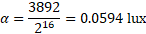
The number of clock cycles per conversion is set at 2^16. This gives a resolution of:
We need to use I2C communication to read the current light sensor reading. As such, light sensor readings can only occur on the main loop. We only read the light sensor reading when the OLED needs to be updated. The actual low light level detection is done using interrupts.
4.6.1 Low light level detection with interrupts
To increase the responsiveness of the system under low light conditions,
we utilize the light sensor’s interrupt function.
For our system, we need to be quickly notified if the light sensor value goes below or above the low light threshold value (LIGHT_LOW_WARNING).
The light sensor will assert its interrupt pin when the light sensor reading is above a high threshold value or below a low threshold value.
However, we can’t determine if the assertion of the interrupt is due to the light level being above the high threshold or because the light level is below the low threshold.
To solve this problem, our code implements two states. These states track whether the light sensor reading is above or below the threshold value.
- State 0 (initial state) -- Light level is currently above
LOW_LIGHT_WARNING.light2notifies theblinkysubsystem of this fact (blinky_disableDark()). The interrupt high threshold of the light sensor is set as high as possible, and the interrupt low threshold is set atLOW_LIGHT_WARNING. Therefore, if an interrupt occurs, it is because the light level went belowLOW_LIGHT_WARNING, and so we transition to state 1. - State 1 -- Light level is currently below
LOW_LIGHT_WARNING. light2 notifies the blinky subsystem of this fact (blinky_enableDark()). The interrupt high threshold of the light sensor is set atLOW_LIGHT_WARNING, and the interrupt low threshold is set as low as possible. Therefore, if an interrupt occurs, it is because the light level went aboveLOW_LIGHT_WARNING, and so we transition back to state 0.
4.8 gterm -- Graphical display subsystem
The gterm subsystem oversees updating the OLED display with the values from the accelerometer (acc2), temperature sensor (temp2) and light sensor (light2) when prompted by hexsec.
The OLED screen is of size 96x64 pixels. gterm divides the screen into a grid of 6x8 characters, giving 16 columns and 8 rows of characters. This division into a grid of characters allows us to avoid the tedious math behind calculating the exact pixel value to place our characters when rendering text.
PIO1_10 (GPIO 2.1) controls the OLED power. As such, we switch it off in STANDBY mode and switch it on in MONITOR mode to switch the display on and off quickly.
We specially wrote our own custom OLED driver code which makes OLED display updates fast. See Section 6.2 (Provided OLED library was slow).
4.10 walker -- Movement detection subsystem
The accelerometer (MMA7455L) in the baseboard supports 3 acceleration ranges for measurement: 2g, 4g or 8g. We have chosen the 2g range since that is sufficient for detecting if there is movement or not. The accelerometer provides measurements as three 8-bit signed integers for each axis (x, y, z). As such, with the range of 2g, the acceleration on a single axis in terms of g can be calculated as:

The accelerometer supports four modes: standby mode, measurement mode, level detection mode and pulse detection mode. When CUTE is in STANDBY mode, our implementation also places the accelerometer in standby mode to reduce power consumption. In MONITOR mode, our implementation places the accelerometer in measurement mode, which allows us to sample acceleration at a rate of around 125Hz. We decided not to use the level detection mode or pulse detection mode as measurements cannot be taken when the accelerometer is in those modes. As such, sampling the accelerometer would require us to temporarily switch back to measurement mode, which would have complicated our code. Furthermore, having access to the raw acceleration values in measurement mode allowed us to implement our own software filters for movement detection.
4.10.1 Reading accelerometer measurements with DRDY
The accelerometer does not provide any guarantees of exactly when a new accelerometer measurement is ready, and so we need to poll for it. Fortunately, the accelerometer outputs a logic high signal to its DRDY pin whenever a new measurement is ready. DRDY is kept high until the measurement is read. As such, our implementation polls the DRDY pin in the main loop, and then proceeds to read the measurement via I2C if it is high. Since GPIO pins can be read with a single instruction, this polling is relatively efficient, and keeps the heavier I2C communication to a minimum. (Note: using GPIO interrupts would be unnecessary, as we would still need to do the actual I2C communication in the main loop)
4.10.2 Movement detection
The (x, y, z) values from the accelerometer provides a 3-dimensional vector.
However, for detecting movement in any direction,
we are only interested in the magnitude of acceleration, in other words, the magnitude of this vector. This can be calculated with sqrt(x*x + y*y + z*z),
but that involves an expensive square root operation.
Fortunately, we do not need to know the actual magnitude of the vector,
as the squared value still exhibits the same patterns doing movement:

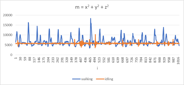
The above plot shows the calculated x^2 + y^2 + z^2 values for two activities:
walking (movement) and idling (no movement).
We can see that both graphs are centered around a certain DC value arising from the constant acceleration due to gravity.
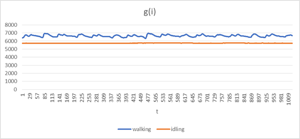
We can derive this DC value by passing m through an exponential moving average filter,
which acts as a low-pass filter:
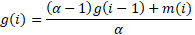
where i is the sample number. By trial and error, we find that α = 100 is sufficient in extracting the DC value from the data, as shown in the plots below:
Subtracting g from m will thus give us the acceleration data centered around zero:
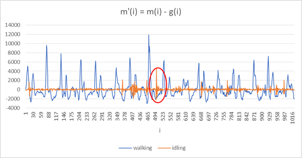
At this point, we can start to see a pattern between walking (moving) and idling (not moving). The values of m’ for walking exceed a lower and upper movement threshold of around ±3000, while the values of idling do not. There are a few visible outliers, though, such as one circled in the plot above where the values of idling exceed the movement threshold, even though no movement is occurring. This is likely due to noise from the accelerometer. We can remove this high frequency noise by using an exponential moving average filter again:
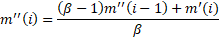
From trial and error, we chose β = 3, which gives us the following plots with all the high frequency noise smoothed out:
This allows us to set the movement threshold to ±3000 to accurately detect movement.
When movement is detected, walker notifies the blinky subsystem (blinky_enableMoving()).
When no movement is detected after a while (300ms), walker notifies the blinky subsystem (blinky_disableMoving()).
6 Significant problems encountered and solutions proposed
6.1 Provided temperature sensor code negatively impacted overall system responsiveness
Initially, we implemented our fire detection by calling the temp_read() function provided by Embedded Artists in our main loop. However, we soon realized that temp_read() negatively impacted the responsiveness of our system.
This is because temp_read() blocks for the whole time where the square wave period measurement is being taken.
e.g. At 30°C, it will block for 505ms just waiting for falling/rising edges!
Since in the main loop only one task can run at any time,
the long blocking time of temp_read() meant tasks from other subsystems could not run,
degrading the responsiveness of our overall system.
Given that all temp_read() does is to wait for the falling/rising edges on the square wave,
we re-implemented the logic using GPIO interrupts which allows our sampling of the temperature sensor to happen constantly in the background,
without affecting the responsiveness of other subsystems.
6.2 Provided OLED library was slow
Originally, our gterm code was based on the OLED display driver provided by Embedded Artists (oled.c),
using its oled_putChar() function to draw our text.
However, we quickly realized that the driver code was extremely slow,
such that we could see the pixels being drawn on the screen.
Since the OLED communication is done on our main loop,
this slowness severely reduced the responsiveness of our system.
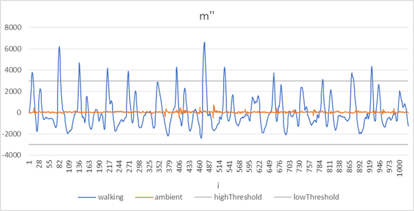
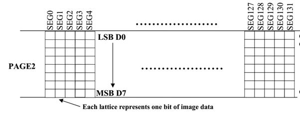
To solve this problem, we first need to understand how the OLED display controller (SSD1305) works. Pixels in the display controller can be directly addressed on the x axis (SEG0 to SEG131), however on the y axis pixels can only be addressed in terms of “pages” (PAGE0 to PAGE7), where each page is 8 pixels on the y axis.
Writing new pixel data (a byte) to the display controller involves specifying the page (PAGE0 to PAGE7) and the segment (SEG0 to SEG131). Data bit 0 of the written byte will be written to the top row of the page, while data bit 7 will be written to the bottom row of the page, as shown in this diagram:
Looking at the code of oled_putChar(), we can see that it calls oled_putPixel() for every pixel drawn.
oled_putPixel() will then transfer the full byte of the page (8 bits) just to update a single pixel (1 bit).
This leads to a lot of redundant transfers (8 times as many transfers than we need),
which thus leads to the slowness of the code.
As such, we optimized the code in our gterm driver by taking advantage of the fact that each character which we draw on the OLED screen is also 8 pixels in height -- the size of a page. As such, when drawing text, we only transfer the full page byte once. This reduces the number of transfers that we do by 8 times, thus speeding up display updates.
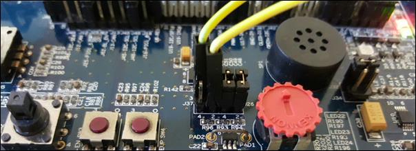
6.3 Accelerometer DRDY pin and Light sensor interrupt pin share the same GPIO line
As mentioned in Section 4.10.1 (Reading accelerometer measurements with DRDY), we poll the accelerometer’s DRDY pin to efficiently check if a new reading is available from the accelerometer. However, both the DRDY pin and the interrupt pin from the light sensor uses the same GPIO pin (PIO2_5). Two devices can’t drive the same pin.
Solution: we attached an external wire to jumper J37, connecting the DRDY pin of the accelerometer to PIO1_8 instead, which happened to be an unused GPIO line.