CG3002 Embedded System Design Project Final Report (Excerpt)
Note
This is an excerpt of the final project report containing only the portions which I wrote and which describe my contributions to the project.
3 Component Interactions and Design
3.1 Main Algorithm
The overall algorithm used for the activity detection is as follows:
- The Arduino samples movement data from the two IMUs at 42Hz (Section 3.3)
- The Arduino pushes the raw movement data to the Raspberry Pi over UART (Section 3.5)
- From the stream of movement data, the Raspberry Pi assembles three segments of movement data. Each segment consists of a continuous window of 42 samples (Section 3.4)
- Extract features from these three segments. Use a trained machine learning model to classify features from the three segments into three actions. If the three predicted actions are not the same, or the confidence level of any of the three predictions is less than 55%, restart from step 1. (Section 5)
- Send the predicted action to the evaluation server. (Section 3.7)
3.2 FreeRTOS on Arduino
A third-party open source FreeRTOS v9.0 AVR port was used to implement the Arduino firmware. Source code is available on GitHub.
Using a real time preemptive multitasking operating system makes it easy for us to implement a system that performs different tasks at the same time (reading sensor data, handling UART communications etc.) while still ensuring that real time requirements are met.
On the other hand, with a preemptive multitasking OS, things get slightly messier when tasks need to interact with each other as we need to take care not to cause race condition bugs. Thankfully, FreeRTOS provides some nice abstractions, such as multi-producer multi-consumer queues which makes things much easier. Still, some Arduino system libraries (e.g. HardwareSerial) were not designed with preemptive multitasking in mind, which caused some race condition bugs to crop up during development (See the Problems Encountered section).
3.3 Processes on Arduino
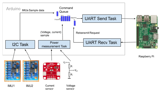
The responsibilities of the Arduino are:
- Sample from the two MPUs at 42Hz.
- Sample from the power measurement signals (current, voltage) at 4Hz.
- Transmit these samples to the raspberry pi over UART. Retransmit any data when requested to by the raspberry pi.
For ease of implementation, the above responsibilities are divided into four separate FreeRTOS tasks.
| Task | Priority |
|---|---|
| UART send | 1 |
| UART receive | 1 |
| I2C communication | 2 |
| Power measurement | 3 |
FreeRTOS Message queues are used for task communication:
- UART send command queue: Contains requests for transmission of a new message or retransmission of a previous message.
UART send task
Consumes from the "UART send queue" and executes transmission/retransmission as required. The task will block if there is nothing to consume.
UART receive task
Receives messages from the raspberry pi. If a "Not-Acknowledged" message is received from the raspberry pi, the task pushes to the “UART send queue” to request the UART send task to retransmit the requested message.
I2C communication task
Handles I2C communication on Arduino’s hardware I2C, in particular, communication with the two IMUs. This task will wake up every 23ms (42Hz) to read a sample from each of the IMUs. It will then push the sample to the UART send queue for transmission to the Raspberry Pi. The task will also detect if the IMUs have been disconnected and will attempt to reconnect and re-initialize them as soon as possible.
As it is important that the IMUs are sampled at regular intervals, the Arduino’s more precise 16-bit Timer1 is used to wake the task up at regular intervals.
Power measurement task
Wakes up every 0.25s to read the power measurement (voltage, current) samples from the ADCs. It will then push the sample to the UART send queue for transmission to the Raspberry Pi.
3.4 Processes on Raspberry Pi
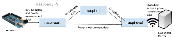
The raspberry pi has the following responsibilities:
- Receive and decode IMU and power measurement data from the arduino over UART.
- Predict the dance move from the IMU data.
- Send the predicted dance move and power measurements to the evaluation server over TCP/IP+wifi.
These responsibilities are split over 3 separate processes which communicate with each other over named pipes:
- UART communication process (raspi-uart)
- Machine learning classification process (raspi-ml)
- Evaluation server communication process (raspi-eval)
One advantage of this multi-process design is that it allows the individual components to be developed and tested independently. raspi-uart and raspi-eval development could be handled by the comms team while raspi-ml development could be handled by the software team without stepping on each other’s toes. Since each process can be tested in isolation, the system is much easier to debug as well as we do not need to setup and run the whole system (Arduino + Evaluation server) in order to test a single component.
The multi-process design is also significantly much more robust compared to a single-process design. In a single-process design, any exception which occurs in the process, even in easily-recoverable areas such as UART or machine learning, will cause the whole process to crash. This will cause the system to disconnect from the evaluation server, which wouldn’t look good. With this multi-process design, if the raspi-uart or raspi-ml processes crashes, they can be easily restarted without disconnecting from the evaluation server. This makes development much easier, as we only need to pay close attention to the stability of the raspi-wifi process.
Finally, this multi-process design allows us to use different programming languages for the different processes. In our implementation, raspi-uart is written in C in order to share the UART communication code with the Arduino. On the other hand, raspi-ml is written in Python 2 for access to the scikit-learn libraries, while raspi-eval is written in Python 3 for ease of implementation. This setup would not have been possible with a single process design.
The disadvantage is that there is memory copying overhead when sending data across pipes. However in practice this overhead is not significant enough to cause issues with performance, vs the other advantages the multi process approach brings.
UART communication process
- Receives messages from the arduino (and requests retransmission if any of them were corrupted/dropped).
- Any power measurement messages will be forwarded to the evaluation server communication process, which will keep track of the present current/voltage as well as the cumulative power.
- Attempts to assemble a continuous window of sensor samples. When the window of 42 sensor samples is successfully assembled, it will then be transferred to the machine learning process for classification.
Machine learning model process
- Receives the sampled & segmented stream of raw data
- Extract feature sets (n-dimensional features) for each window -- this could include the mean, variance, PSD, etc calculated over the the samples in this window
- Filters out noise and outliers from these vectors
- Once clean data is obtained, determines the dance move category this data is associated with and sends it to the evaluation server communication process for transmission to the evaluation server.
Evaluation server communication process
- Keeps track of the present current/voltage as well as cumulative power.
- Receives the classified action from the machine learning model process, and then assembles the update message and sends it to the evaluation server.
Process management
Each of these processes are installed as a systemd user daemon. systemd will run these processes at bootup, monitor the health of the processes, and restart the processes whenever they crash. This helps to ensure that the raspberry pi will operate normally even in the event of sudden process crashes or system resets.
3.5 Communication between Arduino and Raspberry Pi
For communication between the Arduino and Raspberry Pi, we use the following 3-layered protocol:
Layer 1: UART
UART configuration:
- Baud rate: 115200 bps
- 8 data bits, no parity bit, 1 stop bit. (Testing shows that having a parity bit doesn’t help much with synchronization)
This is implemented with the Arduino API on the Arduino mega and the linux serial driver on the raspberry pi.
Layer 2: Packet Layer
Requirements:
- Provide a means to transfer variable-length data sequences from point to point.
- Guide the UART layer to synchronize (find the correct UART start bit) as soon as possible.
- Provide a means to verify the integrity of received datagrams, so that they can be discarded/retransmitted if they are corrupted.
The protocol is similar to the point-to-point protocol (PPP) with a few modifications and additions. It defines:
- A flag byte: 0xFF, chosen as it helps the UART receiver to synchronize, as the start bit will be the only logical low.
- An escape byte: 0x7D.
- CRC-16-IBM checksum with initial value 0xFFFF and (reverse) polynomial 0xA001. (Rationale: simple to compute and AVR libc provides an optimized implementation.)
| Name | Number of bytes | Description |
|---|---|---|
| Start byte | 1 | 0xFF, the flag byte. |
| Information | variable (0 to 255) | Datagram |
| CRC16 | 2 | Frame checksum (uint16_t, network/big endian byte order) |
| End byte | 1 | 0xFF, the flag byte. |
Byte stuffing - On the transmitter’s end, Flag bytes (0xFF) or escape bytes (0x7D) occurring within the datagram or checksum will be replaced with the bytes 0x7D, followed by the original byte with its 5th bit inverted. (i.e. 0xFF -> 0x7D 0xDF, 0x7D -> 0x7D 0x5D). The inverse operation is done on the receiver’s side to get back the original data. This ensures that the flag byte will not occur inside the frame, which will thus allow the receiver to find the correct start byte much more quickly (Kozierok, C. M, 2005).
Layer 3: Message Layer
Requirements:
- Defines message types and adds the ability to distinguish them.
- Enables the raspberry pi to detect dropped packets and request the arduino to re-transmit messages.
This layer defines two message "streams":
- Sample stream, which contains sample data from the two IMUs. If the raspberry pi detects that packets in this stream are dropped, it will request the arduino to re-transmit them. (Rationale: The machine learning classification implementation requires a continuous segment of 42 samples, if a sample failed to be transmitted it would be a waste to drop the rest of them)
- Power measurement stream, which contain the voltage/current measurements. Any messages dropped from this stream will not be retransmitted.
For the sample stream, the following message types are defined:
SAMPLE_NACK(used by the raspberry pi to notify the arduino that a sample needs to be retransmitted)ACC1(Accelerometer values from IMU 1)ACC1_RESEND("resend" variant of the above)ACC2(Accelerometer values from IMU 2)ACC2_RESEND("resend" variant of the above)GYRO1(Gyroscope values from IMU 1)GYRO1_RESEND("resend" variant of the above)GYRO2(Gyroscope values from IMU 2)GYRO2_RESEND("resend" variant of the above)
In other words, a single sample is split into 4 messages (ACC1, GYRO1, ACC2, GYRO2).
This is done to ensure that, in event of packet corruption,
only a small amount of data will need to be re-transmitted
(vs re-transmitting all data of the sample again).
It also defines a "sample ID",
which is an unsigned 8-bit number which increases with every new sample sent.
Since each sample is sent in 4 messages (ACC1, GYRO1, ACC2, GYRO2),
these four messages will have the same “sample ID”.
The "resend" variants are used to notify the raspberry pi that the message is a retransmission -- the raspberry pi should not use its sample id to determine if previous messages have been dropped.
For the power measurement stream, only one message type is defined:
POW(power measurement)
The structures of the message types are as follows. Note that certain message types share the same structure.
| SAMPLE_NACK | ||
|---|---|---|
| Name | Number of bytes | Description |
| Sample ID | 1 | ID of sample that is requested to be transmitted. |
| Message types | 1 | Bitfield of sample messages that need to be transmitted.
If the bit is set, the arduino will retransmit the associated message. Bit 0: ACC1Bit 1: ACC2Bit 2: GYRO1Bit 3: GYRO2
|
| ACC1 / ACC1_RESEND / ACC2 / ACC2_RESEND | ||
|---|---|---|
| Name | Number of bytes | Description |
| Sample ID | 1 | Sample ID the reading belongs to. |
| Message type | 1 | ACC1 / ACC1_RESEND / ACC2 / ACC2_RESEND |
| X | 2 | X value of the raw accelerometer reading. 2's complement, little endian. |
| Y | 2 | Y value of the raw accelerometer reading. 2's complement, little endian. |
| Z | 2 | Z value of the raw accelerometer reading. 2's complement, little endian. |
| GYRO1 / GYRO1_RESEND / GYRO2 / GYRO2_RESEND | ||
|---|---|---|
| Name | Number of bytes | Description |
| Sample ID | 1 | Sample ID the reading belongs to. |
| Message type | 1 | GYRO1 / GYRO1_RESEND / GYRO2 / GYRO2_RESEND |
| X | 2 | X value of the raw gyroscope reading. 2's complement, little endian. |
| Y | 2 | Y value of the raw gyroscope reading. 2's complement, little endian. |
| Z | 2 | Z value of the raw gyroscope reading. 2's complement, little endian. |
| POW | ||
|---|---|---|
| Name | Number of bytes | Description |
| Power measurement ID | 1 | A legacy field, now unused. |
| Message type | 1 | POW |
| Voltage | 2 | Raw voltage reading from the ADC. Unsigned, little endian. |
| Current | 2 | Raw current reading from the ADC. Unsigned, little endian. |
Disconnected IMUs
This layer defines a method in which the arduino can notify the raspberry pi of the connection states of the IMU.
When an IMU is disconnected,
the Arduino will send the [ACC1, GYRO1],
or [ACC2, GYRO2] messages as usual, but their x, y, z values are all zeroes.
The raspberry pi can then take the appropriate action,
such as discarding sample data (since the segment will not contain continuous samples any more).
The special value of zero is used in order not to increase the size of the messages.
Due to the effects of gravity, it is extremely unlikely that for an IMU,
its accelerometer and gyroscope values will all be zero at a given instance.
Retransmission of samples
This layer defines a method for the raspberry pi to request re-transmission of sample message(s) of a sample from the arduino.
Since the sample ID increases with each new sample,
and the arduino will only send the messages [ACC1, GYRO1, ACC2, GYRO2] in sequence once for each sample,
the raspberry pi can determine if any message was corrupted or dropped.
e.g. if it received ACC1 with sample ID 3, and then receives ACC1 with sample ID 4,
then it knows that the messages [GYRO1, ACC2, GYRO2] were dropped or corrupted.
The raspberry pi will then request re-transmission of those messages from the arduino by sending a SAMPLE_NACK message.
The Arduino maintains a circular buffer of samples with a finite capacity, and drops older samples when the buffer is full. If it receives a SAMPLE_NACK message from the raspberry pi, and the sample is still present in the buffer, it will then re-transmit the requested messages of that sample. Otherwise, it ignores the SAMPLE_NACK.
The raspberry pi maintains a queue of incoming samples, both partial (not all messages for that sample received yet), and complete (all messages for that sample have been received). The capacity of this queue is limited, when it reaches it reaches its maximum capacity the queue will drop older samples, even if they are complete.
The queueing system will monitor the number of completed samples received, while re-requesting retransmission of incomplete samples. When a continuous segment of 42 samples have been received, it will then pass it to the rest of the system for processing.
3.6 Coordination between Arduino and Raspberry Pi
Since the arduino's only role is to read inputs from the sensors, there is not much need for fine-grained coordination between the raspberry pi. As such, we have adopted the "push" approach where the arduino will immediately begin continuously pushes data to the raspberry pi on boot without waiting for any acknowledgement.
3.7 Communication between Raspberry Pi and evaluation server
Setup
- The raspberry pi is configured with a known static IP address at its ethernet port. Any computer can connect directly to the ethernet port to configure the raspberry Pi via SSH (no need to connect a screen, keyboard to the raspberry pi). This ensures that only trusted users can change the configuration of the raspberry pi, as users must have physical access to the raspberry pi and know the raspberry pi’s SSH password / private key.
- The raspberry pi can then be configured with the exact wireless network to connect to, the IP address of the evaluation server as well as the secret key to use for AES encryption.
Establishing communications with the evaluation server
- On bootup, the raspberry pi will periodically attempt to establish a connection with the evaluation server. (Evaluation server uses TCP/IP)
- If the connection is every closed unexpectedly by the remote server (i.e.
ECONNRESET), the raspberry pi will periodically try to re-establish the connection.
Communication with the evaluation server
The raspberry pi will send an update to the evaluation server every time a move has been classified.
Each update has the following fields:
- Action (Classified action)
- Voltage
- Current
- Power
- Cumulative Power
The method for sending an update to the server is as follows. It requires a 16, 32 or 64-byte encryption key (known in advance) and a 16-byte initialization vector (IV), which will be randomly generated by the raspberry pi on startup.
Step 1: The data to send to the server is assembled into the following data structure:
| Name | Number of bytes | Description |
|---|---|---|
| Padding | 0-15 | Minimum number of padding bytes to make the total size of this structure a multiple of 16. The byte value can be any value EXCEPT the start byte '#' (0x23) |
| Start byte | 1 | '#' (0x23) |
| Action | Variable | The "Action", as a UTF-8 encoded string. |
| Separator | 1 | '|' (0x7c) |
| Voltage | Variable | The "voltage" in base-10 representation, as a UTF-8 encoded string. |
| Separator | 1 | '|' (0x7c) |
| Current | Variable | The "current" in base-10 representation, as a UTF-8 encded string. |
| Separator | 1 | '|' (0x7c) |
| Power | Variable | The "power" in base-10 representation, as a UTF-8 encoded string. |
| Separator | 1 | '|' (0x7c) |
| Cumulative power | Variable | The "cumulative power" in base-10 representation, as a UTF-8 encoded string. |
Step 2: The above data is then encrypted with AES-CBC using the secret key and IV. This ensures that the data cannot be read by untrusted parties who do not know the secret key.
| Name | Number of bytes | Description |
|---|---|---|
| Initialization Vector (IV) | 16 | IV used to encrypt the data. |
| Encrypted data | Variable | Data encrypted with AES-CBC using the secret key (known in advance) and the initialization vector (generated by the raspberry pi on startup) |
Step 3: The above data is then further encoded into a base64-encoded payload:
| Name | Number of bytes | Description |
|---|---|---|
| Padding | 1 | The byte value is ignored by the receiving server, and thus can be any value. |
| Payload | Variable | Base-64 encoded payload data generated in the previous steps. |
| Padding | 1 | The byte value is ignored by the receiving server, and thus can be any value. |
| End byte | 1 | '|' (0x7C), the end byte. This denotes the end of the payload. |
This final datagram is then written to the TCP stream.
7 Problems Encountered
Below are some of the problems we have encountered and some solutions to take note.
7.4. Race condition in HardwareSerial causes Arduino to retransmit old UART data
During development, we discovered a race condition within the Arduino library's HardwareSerial code which interacted badly with FreeRTOS’s preemptive task switching, causing the arduino to retransmit old UART data. This was because the HardwareSerial code was not written with preemptive multitasking in mind. The occurrence was non-deterministic and was only confirmed by running the Arduino for long periods of time while monitoring the data stream.
We fixed this by wrapping any calls to HardwareSerial with a critical section, which disables interrupts, and thus preemptive task switching, from occuring while HardwareSerial code is being executed. This solved the problem, although it lowers the efficiency of the firmware as high priority tasks may not be switched to in a timely manner.
See this commit for our applied fix, and this GitHub issue for a related bug report.